Wheel Tension App Instructions
The Wheel Tension App (WTA) is a web-based tool that will produce spreadsheets and a visual diagram to help analyze relative tension between spokes (figure 1). Designed to work only with the TM-1 Spoke Tension Meter from Park Tool, the WTA can help you achieve a wheel with consistent spoke tension. It is also useful when diagnosing wheel tension issues or documenting wheel truing results.
NOTE: The statistics generated by the app are based on a factory calibration of the TM-1 Spoke Tension Meter. The values given should be used as a general guideline, as actual TM-1 readings may vary based on the care, history, and usage of any given meter.
Using the Wheel Tension App
- TM-1 Spoke Tension Meter
- Marker to write on rim, or masking tape if desired
- DC-1 Digital Caliper if spoke dimensions are unknown
- Truing stand to hold wheel and spoke wrenches
- Device with internet access (computer or tablet recommended)
With the WTA open, begin with the drop down box under WHEEL SETTINGS. Select the appropriate option from Material. There are five options: Steel, Aluminum, Spinergy PBO, Titanium, and Carbon Fiber Mavic R2R.
- Steel: Stainless steel spokes can sometimes appear similar in color to aluminum. If in doubt use a magnet. Even stainless steel will at least be weakly magnetic. An aluminum spoke will not be magnetic at all. For steel spokes only the WTA can predict and produce Tension Conversion Tables for spokes not found on the chart included with the tool
- Aluminum: The WTA provides only predetermined Tension Conversion Tables which are the same options as the Tension Conversion Tables that come with the tool.
- Spinergy PBO: This is a proprietary material from Spinergy®. Two chart options are provided.
- Titanium: The WTA provides only predetermined Tension Conversion Tables which are the same options as the Tension Conversion Tables that come with the tool.
- Carbon Fiber Mavic R2R: This is a proprietary bladed Mavic® spoke. There is one Tension Conversion Table for this option.
Next, select Shape. For steel, titanium, Spinergy PBO, and aluminum, there are two options: Round and Blade. Blade means flat or “aero” shape.
Manufacturers will sometimes give dimensional specifications of the spoke. However it is always best to measure spokes directly using a caliper. All measurements should be in millimeters, rounded to the nearest tenth. For decimal measurement, use a “dot,” not a comma to designate tenths. In other words, use “1.8” instead of “1,8”.
For round steel spokes, the diameter is referred to as Thickness. Always measure spoke thickness (diameter) near the center, approximately halfway between the rim and hub. Spokes may be butted or thicker at the ends. The TM-1 will be deflecting in the middle section, so measure diameters in the middle.
For steel bladed spokes, you can enter unique numbers for both the Thickness and the Width. The thickness is the thinner part of the spoke, and width is the wider section (figure 2). Titanium, aluminum, Spinergy, and Carbon Fiber Mavic R2R spokes are limited to preset options and you cannot enter any other dimensions.

After WHEEL SETTINGS are complete click on the UPDATE button. The WTA produces a TM-1 CONVERSION TABLE for the spoke data entered (figure 3). These are deflection readings off the TM-1 scale and their corresponding spoke tension in Kilograms Force to that particular spoke.
Conversion tables for steel spokes are calculated based on measurements given by the user, and should be considered approximations of spoke tension. While the printed table represents actual data from the spokes listed, the WTA tables compress and round the data to make it useful for an infinite number of steel spokes. Non-steel spokes do not show this approximation and represent the calibration data as it was taken.
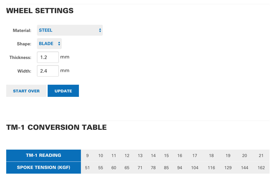
For non-steel spokes, the WTA will show the show only the same charts as the TM-1 Conversion Table that comes with the tool. However, for steel spokes the WTA can predict tension charts for steel spokes not listed on the Conversion Table. This is a very useful feature because there are simply too many bladed options to list on a printed table.
If you are only looking for a rough idea of this spoke’s TM-1 readings and values, you can stop here. Use this table the same as you would one of the columns on the printed TM-1 Conversion Table that comes with the tool.
The WTA features an optional WHEEL TENSION BALANCING function to visualize and document the relative tension between spokes. Begin by entering the number of spokes on the left side of the hub flange. Then enter the number of spokes on the right side. The WTA will produce entry fields for TM-1 readings. Converting your TM-1 reading to corresponding Kgf values will be done by the WTA.
When taking TM-1 measurements, use the rim valve hole as a consistent point of reference. On the wheel left side, spoke #1 is the first spoke to the left of the valve. Move to the left (counter-clockwise) on the left side for spoke #2, #3, etc..
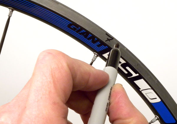
For the right side, spoke #1 is the first spoke to the right of the valve. Move to the right (clockwise) as your measure. To make it easier to track spokes, mark on the braking surface with a pencil/pen (figure 4). This can be removed after the work by solvents such as acetone or even rubbing alcohol. Alternatively you can use tape or just count the spokes from the valve each time.
Take a TM-1 reading of the first spoke and type it into the entry field. Round the deflection readings to the nearest half — it is not realistic to try to be more precise. As an example, you might have a 19, a 19.5, or a 20 deflection reading, but not a “19.23.” Units will automatically be rounded to the nearest 0.5 when you submit the form.
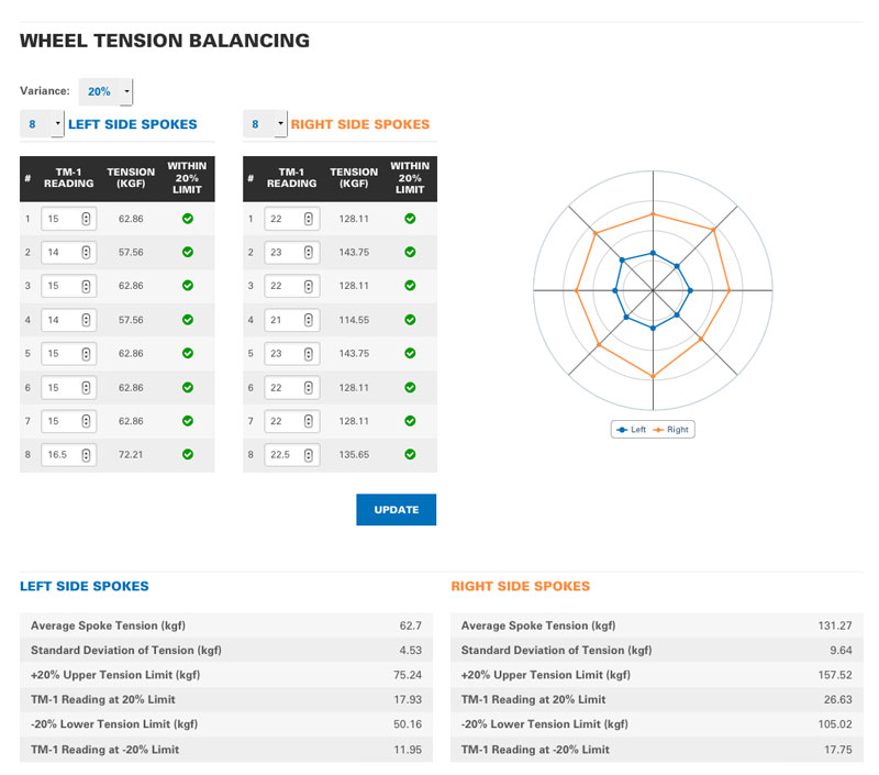
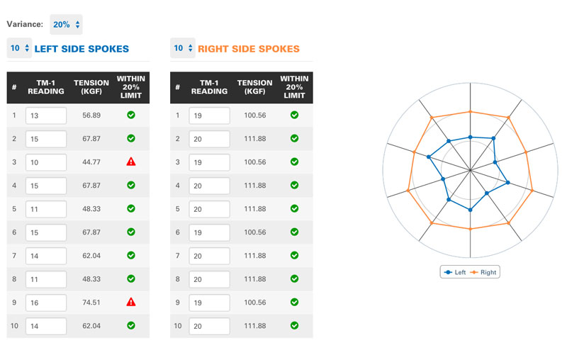
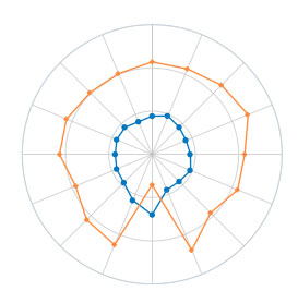
Use the TAB key on computer rather than ENTER to move to the spoke next field. Using ENTER will refresh the screen and process the fields each time, slowing your work. Enter all spokes from one side in the entry fields and then hit ENTER to generate all kgf values for the entry fields. The WTA also produces a visual of radially graphic spoke tension values, called a radar chart. Left side spokes appear in blue and right side spokes appear orange in the diagram.
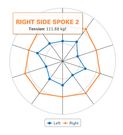
The spoke tensions are data points on the radar chart, with the twelve o’clock position considered spoke #1. When the mouse cursor hovers over data points on the chart, it displays the spoke number and its kgf tension (figure 5).
Spokes with higher relative tension are further from the center of the chart, while relatively looser spokes are closer to the center. It is normal to see radar charts with some anomalies in the shape, looking like “peaks and valleys.” This does not necessarily indicate an unacceptable wheel. The radar chart does not show the trueness or rim runout, it is only showing the relative spoke tension between spokes.
There is an option on the WTA called Variance, which is useful when balancing tension between spokes. Variance refers to the plus or minus tolerance desired in the relative spoke tension. By default it is set to a plus or minus 20% of the average tension. However the mechanic may choose 15%, 10%, or 5% for tighter tolerance balancing work.
Spokes outside of the variance range are identified with an icon on the WTA spreadsheet. A check mark will appear indicating a spoke is within the selected variance, while an exclamation mark indicates it is out of variance (figure 6). This can simply be ignored by the user if desired.
The WTA also generates basic statistics based on the data entered for each side of the wheel (figure 7).
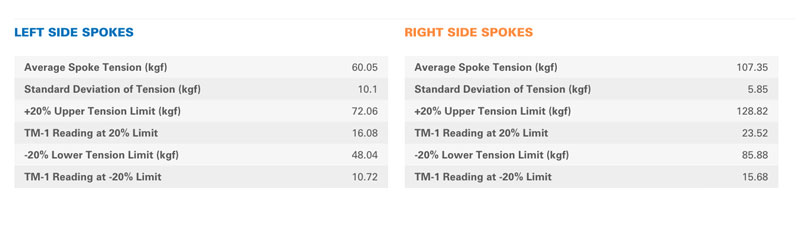
Average Spoke Tension: This is the total of all same-side spoke tensions divided by the number of spokes in the sample. In the example below, the average tension of left side spokes is 60 kgf, and the right side average is 107 kgf.
Standard Deviation of Tension: The standard deviation is the amount of variation from the average. A relatively low number means spoke tensions are all relatively close to the average. A high standard deviation indicates that spoke tensions are scattered over a relatively large range of values. In the example here, the right side spokes are more closely balanced relative to one another compared to the set of left side spokes.
Upper Tension Limit (kgf): The WTA determines the maximum kgf value that is would satisfy the selected variance. For the example, left side spokes above a 72 Kgf reading would exceed the selected a 20% variance.
TM-1 Reading at % Limit: This is the TM-1 deflection reading corresponding to the kgf value of the upper tension variance limit. For the example wheel, spokes reading above a 16 on the TM-1 scale would be above the selected 20% variance. This simply helps to speed the balancing process.
Lower Tension Limit (kgf): The minimum kgf value that is acceptable based on the selected tolerance.
TM-1 Reading at % Limit: The TM-1 deflection reading corresponding to the kgf value of the lower tension variance selected.
The concept of tension balancing is to change and adjust tension between same side spokes so they are relatively close to the same tension. Left side spokes are balanced to other left side spokes. Right side spokes are adjusted to balance to right side spokes. However this should be done so the wheel maintains the same runout (trueness). In balancing it is important to understand that each spoke controls a section of rim, and also shares a “zone of influence” with neighboring spokes pulling on the same side.
By balancing, the wheel will generally stay true longer. If spokes vary widely in tension, even if the wheel is spinning straight, with time and use the rim will loose its true. Loose spokes will tend to get looser, and this can be minimized by balancing the tension. Balancing tension will also maximize spoke life.
Figure 8 below is an example of a rear wheel that spins straight and true. However, notice that right side spoke #4 is tight, while spokes #3 and #5 are relatively lower in tension. Although the rim is spinning straight, spoke #4 is pulling too much compared to #3 and #5. In order to to balance the tension in this situation, the mechanic should loosen spoke #4, while tightening #3 and #5. However, the rim must still spin acceptably straight. Expect there to be a trade-off between a perfectly tension balanced wheel and a perfectly straight wheel.
In balancing, the mechanic makes corrections to spoke tension, check trueness, then takes new measurements. Enter these in the appropriate entry field and use the UPDATE button to see the results.
PRINT WHEELSET DATA
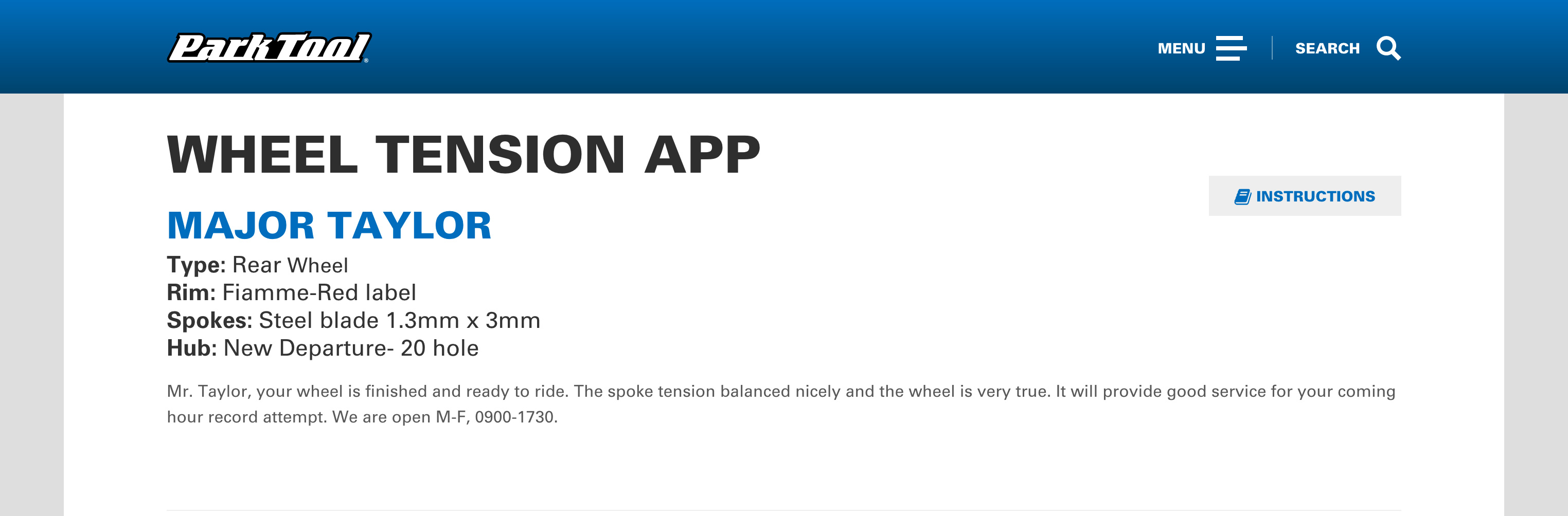
At your option, you can enter data such a user name, rim model, spoke type, hub model, front or rear wheel as well as general notes you consider useful in the fields under PRINT WHEELSET DATA. This will be saved as notes that appear at the top of the WTA for this wheel. (figure 9).
Saving the data
The TM-1 readings and all data can be saved using the SAVE button located below the title: PRINT WHEELSET DATA. This creates a unique URL in the web browser’s address field. Bookmark this page at your option. The link may also be emailed. However, anyone with the URL may change the data as entered for this wheel. It is important to note the WTA only saves online wheel data for one year before it is deleted. Should you want to save this for longer than one year, use the PRINT button and then save as a PDF. It will then be necessary to re-enter the data.
Should you wish to share that data but not allow changes, also send as a PDF by using the PRINT button.
NOTE: Saving and noting the unique URL is the responsibility of the user. Park Tool Company cannot retrieve any data from wheels saved using the WTA.
The SAVE DUPLICATE button creates a different and unique URL but will keep all the data as entered. This is useful if you are servicing a wheel with the same settings, or if you want to compare a wheel over time, say for example after a much hard riding or after a crash.
Understanding Wheel Tension
The TM-1 is a sensitive tool and will show differences in tension between spokes. However, it is not necessary to have all same-side spokes tensioned to exactly the same reading in order to produce an excellent wheel. The rim hoop may have a certain amount of tension from being rolled and joined, or simply may not be perfectly round and flat. Both of these are common issues which prevent a wheel from being perfectly balanced and true. Do not expect a perfect circle on the graph, each same spoke with the exact same tension.
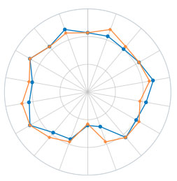
The Wheel Tension App can also be useful in diagnosing and explaining wheel problems. When the wheel has a lateral bend in the rim, it is common to see the left and right side lines cross one another (figure 9). When a wheel has a “flat spot” from a bent rim, the spokes will be lower in tension (figure 8).
Tension Recommendations
It is generally the rim of the wheel that determine acceptable tension, not the spoke itself. Spokes as a rule are capable of handling more tension than the rim. This is why you do not see “spoke tension” specification for the spokes alone.
Manufacturers of rims have set tension recommendations from as low as 80 Kilograms Force to as high as 230 Kilograms force. Generally, the heavier and stronger the rim, the more tension it can handle. A light rim may weigh from 280 grams to 350 grams, while a heavy rim may weigh 450 grams or more. Additionally, rim eyelets may help distribute the load on the rim wall. A lack of eyelets on a light rim may imply that less spoke tension is required. Always consult the rim manufacture for the most up-to-date specifications. Note that manufacturers give specifications for wheels without accounting for tires. Tire pressure effectively lowers the wheel tension, however do not try to account for this drop by adding more tension than recommended by the manufacturer.
The rim manufacturers determine the amount of spoke pulling force in either Kilograms force (Kgf) or in Newtons (N). The mechanic can roughly convert between Kgf and N using a factor of ten. For example, a rim specification of 1100N is approximately 110 Kgf. A more accurate conversion is to use a factor of 9.8, but for quick estimates a factor of ten is sufficiently precise.
Below are rim specifications from select manufacturers. Always check with the manufacturer for the most up to date specifications:
| Make | Model | Front Wheel (kgf) | Rear Wheel (kgf) |
|---|---|---|---|
| Bontrager® | Race X Lite Aero Carbon | 91–136 | 122–181 |
| Race X Lite Aero | 91–136 | 122–181 | |
| Race X Lite | 94–136 | 122–181 | |
| Race Lite Tandem | 100–159 | 100–150 | |
| Race Lite | 77–127 | 86–159 | |
| Race X Lite ATB | 50–132 | — | |
| Race Lite 29-inch ATB, Race Lite 29-inch Disc Compatible | 50–132 | 50–132 | |
| 2003 Race Lite Tubeless, Race Lite Tubeless Disc Specific | 50–132 | 50–132 | |
| Race Tubeless, Race 29-inch Disc Compatible | 50–132 | 50–132 | |
| Select Disc Compatible, Select ATB, Select Hybrid, Select Road | 50–132 | 50–132 | |
| Superstock 29-inch Disc Compatible | 54–132 | 54–132 | |
| Superstock Disc Compatible | 54–132 | 54–132 | |
| Superstock | 54–132 | 54–132 | |
| Campagnolo® | Eurus Wheel | 60–80 | 95–115 |
| Neutron Wheel | 60–70 | 120–140 | |
| Hyperon Wheel | 60–80 | 110–130 | |
| Proton Wheel | 50–70 | 120–140 | |
| Scirocco Wheel | 60–80 | 85–105 | |
| Zonda | Tangent spokes: 60–80 Radial spoke: 75–95 | 90–110 | |
| Mavic® | Crossride® Ceramic | 70–90 | 70–90 |
| Crossride® Disc | 90–125 | 115–145 | |
| Classics SSC® | 80–100 | 80–100 | |
| Crossroc® UST®, Crossroc UST® Disc | 90–120 | 90–120 | |
| Cosmic® Elite | 110–140 | 110–140 | |
| Ksyrium® Elite | 100–130 | 120–145 | |
| Ksyrium SSC | 90–110 | 130–150 | |
| Crossmax SL Disc 07 and SLR Disc | 110–145 | 115–150 | |
| Crossmax® ST Disc | 115–150 | 115–150 | |
| Crossmax ST | 105–150 | 115–150 | |
| Crossmax SLR Disc LEFTY | 110–145 | — | |
| Crossmax® SLR | 100–130 | 115–150 | |
| Crossmax® SX | 105–150 | 105–150 | |
| Crosstrail, Crosstrail Disc | 90–125 | 110–140 | |
| Cosmic® Carbone SL Premium® | 105–145 | 120–160 | |
| Cosmic® Carbone SSC® | — | 130–150 | |
| Cosmos® | — | 100–120 | |
| Shimano® | WH-M959, WH-M575, WH-M540 | 98–118 | 105–128 |
| WH-M7701 (also for carbon) | 105–160 | 98–140 | |
| WH-7700 and 6500 | 98–118 | 105–128 |
Related articles
Spoke Tension Measurement and Adjustment View Article
Wheel Truing (Lateral & Radial) View Article
Wheel Dishing (Centering) View Article